|
FREE-FORM OPTICAL COMPONENTS IN SOME EARLY COMMERCIAL PRODUCTS
William T. Plummer
President, WTP Optics,
Inc.
Sometime Senior Director
of Optical Engineering, Polaroid Corp.
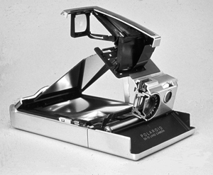
The Polaroid SX-70 folding Single Lens Reflex camera was introduced in 1972. Because
of its peculiar off-axis viewing optical system, we used two free-form optical components
in its optical design. One large free-form surface, deployed on the eye lens, corrected
for field tilt and localized apparent power and astigmatic errors across the viewed
scene, relayed from a textured Fresnel field mirror focus screen. The other free-form
surface, a small corrector plate located just at the real aperture stop, mainly corrected
the net coma and spherical aberration common to all of the field. These two surfaces
were optimized along with an off-axis aspheric concave mirror to provide a well-corrected
system.
 The eyelens free-form surface functioned much
like a familiar progressive-power spectacle lens, or smeared-out bifocal lens. The
concept for such a lens goes back about a century, but the optical requirements for
designing a good one were laid out by C. W. Kanolt in a 1959 US Patent. The eyelens
surface used by Polaroid was different from Kanolt's in several important ways; one
difference was the use of a single 6th-order analytic polynomial expression for the
entire surface, giving the depth Z as a function of both X and Y across the area. The eyelens free-form surface functioned much
like a familiar progressive-power spectacle lens, or smeared-out bifocal lens. The
concept for such a lens goes back about a century, but the optical requirements for
designing a good one were laid out by C. W. Kanolt in a 1959 US Patent. The eyelens
surface used by Polaroid was different from Kanolt's in several important ways; one
difference was the use of a single 6th-order analytic polynomial expression for the
entire surface, giving the depth Z as a function of both X and Y across the area.
All such free-form surfaces require special means for fabrication. Even with a
CNC grinding machine of sufficient precision, the tool path required has to be developed
mathematically in three dimensions to allow for the finite size and actual shape
of the grinding tool. The tool path can be constructed in various ways, as may be
most suitable for the machine to be used, but all depend on the fact that every element
of the optical surface will be tangent to the grinding tool at some time in the generation
process. There is then an option of making each cutting path a planar curve, if that
is more suitable for the machine, or alternatively of spacing the cuts equally on
the work surface with a more complicated tool motion.
After it is polished with a soft lap, the free-form shape must be measured against
a relevant functional tolerance before it is placed in volume production. We evaluated
the eyelens surface for local dioptric errors, calculated in an array of eye-sized
regions across the surface, simply by applying Kanolt's equations to our 3D profilometry
data. For system tooling qualification the assembled camera system was evaluated
in much the same way, but with a visual technique applied successively to a 2D array
of bright points in the subject plane. Profilometry measurements were made with special
machines designed and built by our group.
Initially our free-form molded optics were controlled in production by the use of
interferometry or contact test plates on the flat or spherical side of each piece,
but this method did not perfectly define the parts. By 1980 Steve Fantone had developed
a means of using holographic interferometry to test our molded free-form lenses.
We had considered that we could use a computer-plotted hologram for this purpose,
or could make a hologram photographically from a single near-perfect optical part
-- but Fantone realized that the test hologram could also be made more easily from
a near-perfect mold cavity, if we just selected the proper diffractive order
when we used it. His method is described in US Patent #4,396,289. This test provided
a simple and familiar way to check the quality of manufactured free-form product.
The familiar large-format Polaroid cameras typically had f/8 to f/10 taking lenses.
We once manufactured three-element and four-element designs lens to correct the aberrations
and provide compact and convenient front-element focus adjustment. But these
designs are quite sensitive to accurate centering of the inner negative elements,
at the risk of significant field tilt, or differential focus, across the area of
the film. We realized that a simpler aspheric meniscus landscape lens would
perform nearly as well, except for loss of the focus adjustment benefit. Such
a lens was introduced in the 1977 OneStep camera, a fixed focus model, and has been
used since then in newer camera models. In 1981 we provided sonar automatic
focus by adding a four-zone rotating turret lens at the aperture stop.
In 1986 Polaroid introduced the "Spectra" camera. As contrasted with
the earlier instant cameras, the film area was larger, the focal length was longer,
the corners were kept brighter, and distortion was better corrected. The longer
focal length required more zones of focus. There was no space for a larger
zone turret, so we combined the aspheric-meniscus scheme with a close pair of unique
free-form optical surfaces, called "Quintics", capable of a compact continuous focus adjustment from 60cm to infinity. continuous focus adjustment from 60cm to infinity.
The concept behind this free-form focus design dates to a 1926 British patent awarded
to a Kyoto physician, Isao Kitajima. This same idea was rediscovered or elaborated
in various ways by Birchall in 1935, by Lewis in 1941, by Alvarez in 1967 and in
1970, and by Baker in 1971, 1984, and 1987. Our 1987 version used in the Spectra
camera differed from the earlier proposals by using a pivoting motion to rotate one
free-form optical shape across the aperture, an important mechanical convenience,
but a change that removed even the mirror-symmetry common to all the previous designs.
The Spectra cameras offered 10 zones of focus by pivoting a moving lens only 2.5
apertures long. The companion fixed free-form component not only cancelled
the coma that would have been produced by the moving component, but carried a rotationally
symmetric asphere superimposed on its surface as well.
Although it was mathematically complex, with polynomial terms up through 8th order
and some 44 numerical coefficients used to define each of the paired analytic
surfaces used for focus, the Spectra camera was refreshingly easy to manufacture.
Unlike the earlier camera lens designs with three and four elements, there was no
need to make a final focus adjustment on the system; the parts of the taking lens
were literally snapped together as the camera was assembled! Because the optical
correction did not depend upon cancellation of large aberrations among the multiple
elements, as in conventional photographic lenses, placement tolerances were also
looser.
Even with free-form optics inside it, the completed Spectra taking lens may be tested
on a standard nodal-slide optical bench or with MTF equipment just as any other assembled
photographic lens is tested, but of course should be tested at more than one focus
setting. Unlike front-element focus or conventional unit focus, achieved by
motion of an entire taking lens, the Quintic focus motion actually adds and subtracts
refractive power in the system, so the net Petzval curvature changes with focus setting,
and may ultimately limit the focus range that will be acceptable.
Twelve to sixteen cavities were used for molding each of the lens components.
To avoid having to match components by cavity identification for assembly, parts
from all cavities were tested sequentially, replacing one component at a time in
a standard complete set, to assure that the molded parts were fully interchangeable.
Where differences in refractive power were found, they were corrected by simple adjustment
of power: by altering the spherical or flat surface on the reverse side of
each mold cavity until all the molded parts matched.
Polaroid introduced two more free-form optical components in 1992 in the viewfinder
of a small-format folding camera called the "Captiva" in the United States,
but "Vision" and "Joycam" in other places. It used a catadioptric
SLR system somewhat like the one in the older SX-70, but without a focus-screen texture
on its Fresnel field mirror and without an aperture stop to hold an aspheric corrector.
Instead, the concave mirror and one eyelens surface were made free-form to optimize
the design.
These six different free-form optical components introduced from 1973 through 1992
were all manufactured in the millions by injection molding from ground and polished
stainless steel tools, all made on commercial three-axis CNC machines or on granite,
air slide, and interferometric machines specially designed and built for the purpose
by our group at Polaroid.
Several other free-form components were also made at Polaroid, including a pair of
linear-translation aspheres used as part of a Polaroid zoom macro camera, two pairs
of semiconductor lenses used in a military infrared zoom camera by Rochester Photonics,
and a number of cubic phase masks made for CDM Optics. The smaller parts and
their molding tools were generated by diamond turning on a precision lathe equipped
with a synchronized fast-tool servo. This latter technique even provides a
way to make prototype optical parts quickly in plastic without having to build a
mold.
Early free-form optical components made commercially by others include a few generations
of progressive-power spectacles, a convenient eye testing machine based on Bill Humphrey's
observation that the "Alvarez" lens could also provide any amount of cylindrical
power if its halves were displaced crosswise to their spherical power adjustment,
and an interesting lens made by Tinsley Labs to improve the photographic placement
of color phosphor patterns on color CRTs by enabling light to follow the same contorted
path as the electron beams.
The free-form optical work done at Polaroid has been documented in several publications,
each of which references some others:
- Plummer, W.T., "Unusual Optics of the Polaroid SX-70 Land Camera" Appl.
Optics 21(2), 196-202 (1982)
- Plummer, W.T., "The SX-70 Camera: The Optics" Optics &
Photonics News 5(10) 44-48 (Oct., 1994)
- Plummer, W.T., J.J. Mader, J.W. Roblee, and J. Van Tassell, "Precision Engineering
at Polaroid" Proc. of the Pre-Conf. Day, pp. 24-29, Precision Engineering
in Industry 3 International State of the Art,
Eighth Int. Precision Eng. Seminar, Université de Technologie de Compiègne,
France; M. Bonis, et al., Ed. (May 15, 1995). (Because this publication may be difficult
to locate, it is available in html form on this web site at http://www.WTPOPTICS.com.)
- Plummer, W.T., J.G. Baker, and J. Van Tassell, "Photographic Optical Systems
Using Nonrotational Aspheric Surfaces" Appl. Optics 38(16)
3572-3592 (1999)
- Fantone, S.D., U.S. Patent #4,396,289, "Method and Apparatus for Holographic
Testing of Optical Components", August 2, 1983
VIEW the annotated pictorial slides
as HTML

|